Contents
3 - External Interface Requirements
1 - Document Overview
1.1 -
Purpose
This
document provides an outline of the St Vincent Driving Simulator as a whole and
describes the first iteration of development to create a functional prototype.
1.2 -
Document conventions
This
document describes the components of the St Vincent Driving Simulator in 6
sections ranging from General Overview and Functional Requirements to
Non-Functional Requirements.
In a
couple of the sections in this document, namely Sections 2 and 4, exists the
bulk of the implementation and design for the project respectively.
1.3 -
Intended audience
Project
Managers
Development
Team
Users of
this software with the goal of modifying its structure
1.4 -
Additional Information
As an
open source project hosting has been provided by Sourceforge.net
SVN: https://svc-driving-sim.svn.sourceforge.net/svnroot/svc-driving-sim
Web: http://svc-driving-sim.sourceforge.net/
In
addition to an external steering wheel interface DarkGDK will be used as a
front end to DirectX to aid in the creation of a 3D environment.
Definitions
For definition of common terminology used in this document please
refer to Section 6 Appendix A.
License
This work uses the Creative Commons Attribution-Share Alike 3.0
United States license which can be reviewed in Section 6 Appendix B.
1.5 -
Contact information/SRS team members
Project
Development
Paul
Scarrone
Email:
Paul.Scarrone@email.stvincent.edu
Anthony
Williams
Email:
anthony.williams@email.stvincent.edu
Josh
Woods
Email: josh.woods@email.stvincent.edu
Nathan
Hoffer
Email: nathan.hoffer@email.stvincent.edu
Riley
Hardin
Email: riley.hardin@email.stvincent.edu
Sarah
Anderson
Email: sarah.anderson@email.stvincent.edu
This
Documentation
Paul
Scarrone
Email:
Paul.Scarrone@email.stvincent.edu
Anthony
Williams
Email:
anthony.williams@email.stvincent.edu
Josh
Woods
Email: josh.woods@email.stvincent.edu
Nathan
Hoffer
Email: nathan.hoffer@email.stvincent.edu
Riley
Hardin
Email: riley.hardin@email.stvincent.edu
Sarah
Anderson
Email: sarah.anderson@email.stvincent.edu
Brendan
Bartko
Email: brendan.bartko@email.stvincent.edu
2 - Product Overview
2.1 -
Product perspective
The St. Vincent College Driving Simulator is an interdepartmental
project between Dr. Mark Rivardo of the Psychology department and the Computer
Science department under the supervision of Dr. Cynthia Martincic. The
Psychology department requested a system to generate reliable reports based
upon human reactions to stimuli in the form of driver distractions. Currently
the department uses a manual approach to distract and to gather statistics
through interacting with the subject and observing the subjects reaction times.
A system was desired to allow for my systematic and accurate tracking of test
data. Through consultation with Dr. Mark Rivardo it was discovered that a new
system would have to be created to meet these needs. The application would be
required to us 3D computer technology to generate an environment for testing
and an accurate system to track and report the test subject. The decision was
made to use the DarkGDK library in C++ to reduce the start-up time regarding
the 3D requirements of the simulator. As a student project there is an absence
of experience required realize this as a complete application, but it will be
possible to create an initial proof of concept that can act as a prototype
solution with the most essential requirements met. This prototype will be
essential for continued development and a final deliverable.
2.2 -
Product functions
2.2.1 - Use Case Related to Driving
2.2.1.1 - First Person
Driving
Use Case
The user shall view the driving course and all events generated by
the system from the first person perspective as if in the driver’s seat of a
car. The primary purpose of requiring a first person perspective is to greater
the immersion of the user in the experience of driving. While this is a
simulation, a properly maintained suspension of disbelief should provide
greater accuracy in testing results.
Description
Additional factors that attribute to the goal of immersing the
user in the simulated driving experience are those items which are related
experientially to the act of driving; Speed, Acceleration, Turning Rate,
Turning Pivot, Braking, and Field of View.
2.2.2 - Use Case Relate to First
Iteration
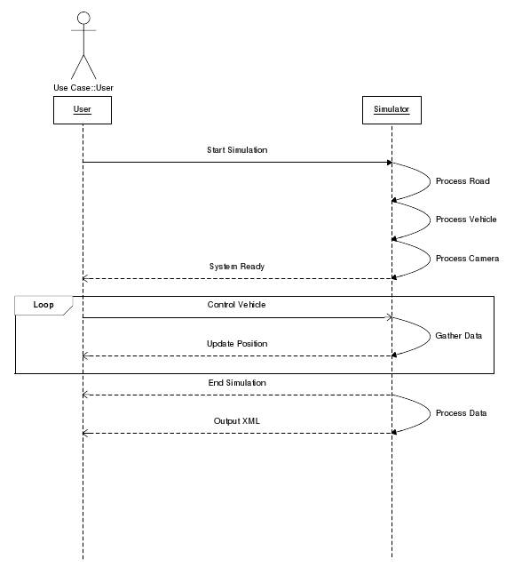
2.2.2.1 - Prototype
Use Case
The end user is not the target of this
use case. The target is to provide a functional system that can guarantee the
viability of the project. This is accomplished by proving that a 3D environment
can be created, relevant data can be tracked and manipulated, and accurate reports
can be generated from each simulation session.
Diagram
2.2.2.1.1
2.3 -
User Classes and Characteristics
2.3.1 – CoordBlock
Struct
Vertex3d:
Purpose:
The Vertex3d struct stores three values that represent a vertex in
three dimensional space.
Code Description:
The Vertex3d struct contains three float variables named “x”, “y”,
and “z” each corresponding to a coordinate value in a vertex.
Struct
Vertex2d:
Purpose:
The Vertex2d struct stores two values as a vertex in two
dimensional space.
Code Description:
The Vertex2d struct contains two float variables named “x” and “y”
each corresponding to a coordinate value in a vertex.
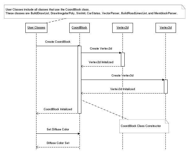
Class
CoordBlock:
Purpose:
The purpose of the class CoordBlock is to allow the classification
and storage of all the necessary coordinate information in the form that the
MemBlock can utilize to create a mesh. A key aspect of this class is its
ability to create a CoordBlock object from vertex and diffuse color values for
a coordinate. The vertex value can be in the form of a Vertex3d struct or in
the form of three distinct float values.
Requirements:
This class uses Vertex2d and Vertex3d structs in its private
members.
Code Description:
There are two constructors for creating objects of the class
CoordBlock. In the first constructor, three float values, each corresponding to
a coordinate in a three-dimensional vertex, and a Boolean value can be passed
into the constructor. The Boolean value indicates whether or not to complete
the remaining CoordBlock private members through instantiation. In the second
constructor, a Vertex3d and diffuse color are passed to initialize all of the
private members of the CoordBlock class. There are also two functions that help
complete the instantiation of CoordBlock private members. The last function is
applied by setting the CoordBlock’s diffuse color to the diffuse color passed
into the function.
2.3.1.2 - CRC
Vertex2d
Struct Properties:
float x
float y
Vertex3d
Struct Properties:
float x
float y
float z
CoordBlock
Class Properties:
Vertex3d vertex
Vertex3d normal
Vertex2d uv
DWORD diffuse
Method Prototypes:
CoordBlock()
CoordBlock(float x, float y, float z, bool autoComplete)
CoordBlock(Vertex3d vertex, DWORD dColor)
void CompleteCoordBlock(Vertex3d vertex)
void CompleteCoordBlock(Vertex3d vertex, float z)
void SetDiffuseColor(DWORD diffuse)
Inheritance
None
2.3.1.1 - Sequence Diagram
2.3.2 - DoubleLinkedList
Purpose:
This class is a templated doubly linked list class.
Requirements:
This class has no requirements.
Code Description:
This class contains a node structure that holds Node data, a
pointer to the previous node, and a pointer to the next node. Basic linked list
functions such as push_back(T), push_front(T), pop_back( ), pop_front( ),
CopyList( ), empty( ), and GetSize( ) perform the actions described by their
names. The function CopyList copies a list by creating a new DoubleLinked list
of length GetSize, traverses the existing DoubleLinked list, and adds equivalent
values of existing items to the new linked list as it processes.
2.3.2.2 - CRC
Class Properties:
struct node
node* head
node* tail
int size
Method Prototypes:
DoubleLinked()
DoubleLinked(Array[N])
bool empty()
void push_back(Data)
void push_front(Data)
Data pop_back()
Data pop_front()
void CopyList(DoubleLinked)
int GetSize()
~DoubleLinked()
Inheritance:
None
2.3.2.1 - Sequence Diagram
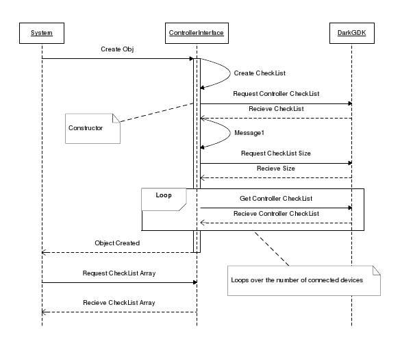
2.3.3 – ControlDeviceManager
Purpose:
This class provides a wrapper for existing DarkGDK systems
involving the polling of Direct Input compatible controllers. In DarkGDK items
polled from DirectX are ordered into an internal CheckList structure that gives
access to the items name and up to 4 attributes about the item polled. To make
handling selection of a controller less complicated s structure is defined to
hold the item name and up to 4 attributes that can be accessed as an array of
objects. Array creation is handled by this class and provides methods of
external access.
Requirements:
This class depends upon the DarkGDK subsystem and compatible
DirectInput devices.
Code Description:
This class carries its own definition for a structure which
contains the options that DarkGDK extracts when polling and creating an
internal Checklist. This class consists of a single constructor which upon
instantiation completes the checklist object. This class contains, 2 accessor
functions for the checklist size and to access the checklist itself and 2
methods. These methods handle the initial polling of the system for devices and
the passing of that information into the checklist structure. The code flows
from this constructor directly to these two methods in series without the need
for input from the user. At any time, if a re-polling must be done, the checklist
can be recreated without the need of a new object by using the
CreateCheckList() method at any time from the original object.
2.3.3.1 - Sequence Diagram
2.3.3.2 – CRC
Class Properties:
int size
CheckList* checkList
Method Prototypes:
ControlDeviceManager()
void CreateCheckList()
void ProcessCheckListItem()
Checklist* GetCheckList()
int GetCheckListSize()
Inheritance:
None
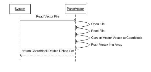
2.3.4 – ParseVector
Purpose:
The
purpose of the class ParseVector is to allow a file that contains vector points
of x, y, and z coordinates to be read and correctly stored in an array in order
for these vector points to be utilized by other classes in the project.
Requirements:
It
is important to note that for the vector points to be read in by the program properly,
there must be a comma after each coordinate in a vector point, including the
last coordinate (e.g. “1, 2, 3,”). In addition, after the comma of the last
coordinate of a point a new line is started for the next new vector point, and
there is no new line after the last vector point in the file. Each vector point
is expected to have three coordinate values, one x, one y, and one z.
Creating Points for the Vector:
This
information is not essential to the program correctly working but aids whoever
may need to create vectors with new points. Begin with the initial point of the
vector as the point (0, 0, 0). Then with a graphing device (such as a graphing
calculator), graph a circle with a radius of ten and make its center the
previous initial point (0, 0, 0). Trace along the circumference of the circle
and select a point. This selected point is the next new vector point. Thus, add
this new point to the text file containing the list of vector points. Use as many decimal places as possible when
recording the vector points in order for the vector points and calculations
with the vector points to be very precise. Next move the circle with a radius
of ten so that the center of the circle is at the new vector point. Then
repeating the process before, select another point from along the
circumferences of the circle as the next new vector point. Repeat this
procedure of translating the circle and selecting and recording a new vector
point until there is a total of ten vector points in the vector points list in
the text file.
Code description:
A
key functionality of this class is reading in a text file. This is accomplished
by using the fstream library class. Using fstream, the appropriate indicated
text file can be opened by the ParseVector class, and then each line is read in
by the fstream function getline(). The
result of the getline() function is returned in a character array which is
stored in a temporary variable and used to translate the data into a string,
which is stored in another string variable. Then using character array of the
single line of data, each character is tested to see if it matches a comma. If
a comma is found, then the substring function is used on the variable
containing the string of line data, utilizing a variable that stores the
desired start position for each substring and the current position in the
character array. The value extracted from the string is then converted into a
float value. Then according to the indicator variable, which indicates the
coordinate in the vector that has been extracted (0 for x, 1 for y, and 2 for
z), this float value is stored into the correct position in an array as the
appropriate coordinate of a vector point. This process is continued until the
end of the text file is reached, indicating all the data has been read and
stored in the array. An additional functionality of the class is that a
CoordBlock array can be built from the Vertex3d array used to store all the
vector points from the text file. This is accomplished by passing in a
CoordBlock array by reference and then adding the appropriate point data from
the entire Vertex3d array to the CoordBlock array. Thus after all the Vertex3d
array data has been inserted into the CoordBlock array, the completed
CoordBlock array is passed back by reference and can be utilized by the other
classes in the project.
2.3.4.1 - Sequence Diagram
2.3.4.2 – CRC
Class Properties:
Vertex3d* vectorPoints
CoordBlock* coordArrayTemp
int arraySize
DWORD diffuseColor
Method Prototypes:
ParseVector()
ParseVector(char* filename)
void ProcessVectorFile(char* filename)
void SetDiffuseColor(DWORD color)
int GetVectorFileLength(char* filename)
int GetArraySize()
void GetVectorCoordBlock(CoordBlock (&coordArray2)[N])
void CopyVectorCoordBlock()
Inheritance:
None
2.3.5 - DrawIrregularPoly
Purpose:
As
a final step in the road generation process this specialized class passes data
into a DarkGDK MemBlock structure for use in creating a static reusable mesh
from a single series of spatial coordinates. All constituent requirements to
handle MemBlock data are completed in this class but creation of the MemBlock
is reliant on additional external classes.
Requirements:
Since
this class does not perform any data processing it requires in its overloaded
form an array of points that it can pass to the BuildDrawList class and parse
through the list of spatial objects it receives in return. MemBlock size and
position information is calculated by knowing the initial size of the data set
being passed int to the constructor. Also due to this being the final step in
creating a mesh object this class creates a formatted data file of all
positions for each vertex within the new mesh alongside the creation of the
MemBlock. There are no sequence requirements for a MemBlock, so the data must
be in the correct order when brought in for processing.
MemBlock Criteria:
MemBlocks
are a binary file format with a 96bit header followed by 288bits multiplied by
the number of vertices in the original input. This file type can be manipulated
both as a binary file and as a memory object and then converted into a static
mesh represented as a single object. MemBlock size is represented in bytes
using the equation [96bit + ( Number of Vertices x ( 3 x 96bit)] / 8bit
MemBlock Specification:
|
MemBlock
Header Information 96 Bits |
|||
|
Type |
Value |
Hex |
Description |
|
Dword |
338 |
52 01 00 00 |
FVF Format Type
(Flexible Vertex Format) |
|
Dword |
36 |
24 00 00 00 |
FVF Size – The size
of a block of coordinates |
|
Dword |
6 |
06 00 00 00 |
Number of Vertices
(VertexNum) |
|
Coordinate
Block (FVF Size * (3 * 96)Bits --- Repeats a VertexNum number of times |
|||
|
Spatial
Coordinates |
|||
|
Float |
5 |
00 00 A0 40 |
Vertex X |
|
Float |
5 |
00 00 A0 40 |
Vertex Y |
|
Float |
0 |
00 00 00 00 |
Vertex Z |
|
Normals
Coordinates |
|||
|
Float |
5 |
00 00 A0 40 |
Normal at Vertex X |
|
Float |
5 |
00 00 A0 40 |
Normal at Vertex Y |
|
Float |
0 |
00 00 00 00 |
Normal at Vertex Z |
|
Diffuse
Color |
|||
|
Dword |
1065353216 |
00 00 80 3F |
Object color under
white light |
|
UV
Coordinates |
|||
|
Float |
0 |
00 00 00 00 |
UV at Vertex X |
|
Float |
5 |
00 00 A0 40 |
UV at Vertex Y |
Sample
MemBlock generated by DarkGDK :
52 01 00 00 24 00 00 00 06 00 00 00 00 00 A0 40 00 00 A0 40 00 00 00 00 00 00 A0 40 00 00 A0 40 00 00 00 00 00 00 80 3F 00 00 00 00 00 00 A0 40 00 00 A0 C0 00 00 A0 40 00 00 00 00 00 00 A0 C0 00 00 A0 40 00 00 00 00 00 00 80 3F 00 00 00 00 00 00 A0 40 00 00 A0 C0 00 00 A0 C0 00 00 00 00 00 00 A0 C0 00 00 A0 C0 00 00 00 00 00 00 80 3F 00 00 00 00 00 00 A0 C0 00 00 A0 40 00 00 A0 40 00 00 00 00 00 00 A0 40 00 00 A0 40 00 00 00 00 00 00 80 3F 00 00 00 00 00 00 A0 40 00 00 A0 40 00 00 A0 C0 00 00 00 00 00 00 A0 40 00 00 A0 C0 00 00 00 00 00 00 80 3F 00 00 00 00 00 00 A0 C0 00 00 A0 C0 00 00 A0 C0 00 00 00 00 00 00 A0 C0 00 00 A0 C0 00 00 00 00 00 00 80 3F 00 00 00 00 00 00 A0 C0
Code Description:
The
class directly pushes the objects from a list type to a MemBlock. Upon
overloaded instantiation class calculates the size of the MemBlock and writes
the header followed by the objects spatial coordinates in series. Writing
position is handled by absolute location based upon the sequence number of the
item being written to MemBlock. Sequential item position is handled by
positioning the MemBlock pointer the distance in bytes of the last data item
entered. Once completed the MemBlock is dumped to a file automatically so an
object can be created without reprocessing.
2.3.5.1 - Sequence Diagram
2.3.5.2 – CRC
Class Properties:
int fvfStyle
int fvfVertexSize
Method Prototypes:
DrawIrregularPoly(CoordBlock (&coordArray)[N])
DrawIrregularPoly(DoubleLinked<CoordBlock> &list)
void MakeMemBlockIntoFile(int memblockIndex, char* filename)
void WriteFVF338Header(int memblockIndex, long vertexNum)
int CalcMemBlockSize(int vertices)
void WriteCoordBlock(int blockNum,CoordBlock cBlock, int
memblockIndex)
Inheritance:
None
2.3.6 - MemblockParser
Purpose:
The purpose of this class is to simply read in information from a
file and construct a MemBlock. Once the
MemBlock is created, it is pushed into a list of type CoordBlock. After the information is pushed into the
list, the created MemBlock is destroyed.
This class efficiently creates the CoordBlock list to aid in creation of
the road.
Requirements:
This class requires the information being read in from the file to
be in the correct format. The
information must have a header which will tell how many vertices must be read
in. This class also requires the use of
its overloaded constructor.
Code Description:
First, the code sets up a structure for the MemBlock healer. It includes the fvfStyle, fvfVertexSize, and
the vertexNum. Then, the code begins
reading in the information from the file.
The memblockId is created along with the header for the MemBlock. Once the foundation is created, the
information is read into the MemBlock.
Then, the MemBlock is created and is pushed into the list of type
CoordBlock. Finally, the MemBlock is
deleted.
2.3.6.1 - Sequence Diagram
2.3.6.2 – CRC
Class Properties:
int memblockId
DoubleLinked<CoordBlock> list
CoordBlock tempCoordBlock
MemblockHeader header
Method Prototypes:
MemblockParser()
emblockParser(int memblockId)
void ReadFVFHeader()
void ReadMemblock()
MemblockHeader GetFVFHeader()
Inheritance:
BuildRoadLinesList
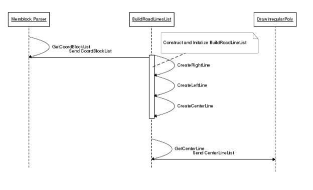
2.3.7 - BuildRoadLinesList
Purpose:
The purpose of this class is to accept a passed DoubleLinked
CoordBlock list and from this list build the right, left, and center line
drawing lists. The passed DoubleLinked CoordBlock list is the list containing
the drawing order of the vertices of the road surface. The class uses this list
for each road line by looping through the drawing order list, selecting the
correct vertex, and storing the vertex in the appropriate road line drawing
list. After a BuildRoadLinesList object is constructed and initialized, the
object will store three separate DoubleLinked CoordBlock list, one for each
road line. The class allows the road line drawing lists to be utilized by other
class by having an accessor function for each road line draw list.
Requirements:
In order for this class to work appropriately, the DoubleLinked
CoordBlock list passed in for construction or initialization must be the
correct drawing order list for the road surface. This is necessary because the
road’s vertices are stored in a specific pattern which is then used by this
class in selecting the right vertices for each road line drawing list. Using
any other DoubleLinked CoordBlock list or format for the list will result in
road lines that will not appear correctly on the roads surface. The suggested
way of attaining the proper DoubleLinked CoordBlock road surface drawing list
is with the GetCoordBlockList(DoubleLinked<CoordBlock> (&list2))
function of the MemblockParser class.
Code Description:
This class is functional only after it has been initialized by
using the DoubleLinked CoordBlock drawing order list. This process of
initialization is a separate function within the class. This initializing
function accepts the drawing order list and creates another version of the
drawing list as an array. It is significant that the drawing list is available
within the class as an array because when the drawing list is processed later
in the class, the array data structure will allow easy access to CoordBlock
data at the calculated positions in the list.
Within the initializing function, there are three function calls that
are made to build each road line drawing list. These three distinct functions
are similar in the manner in which they process the drawing order list to build
the proper drawing order list for each road line. The implementation pattern
these three functions follow include calculating the appropriate position in
the drawing order list for the needed CoordBlock vertex data, looping through
the class’s array version of the drawing order list to the calculated position,
storing the CoordBlock vertex data in a temporary variable, changing the
temporary variable’s z-value to -0.1, and storing the temporary variable in the
correct road line’s drawing list. The reasoning behind changing the z-value of
each road line CoordBlock vertex is that for the road lines to appear on the
screen, the lines must be draw slightly above the road surface. Therefore by
making the z-value of the road lines all -0.1, the lines will be above the road
surface, which is drawn with vertices that have a z-value of 0. It might seem
counterintuitive that a negative z-value is above a non-negative z-value.
However, this is how the z-axis is arranged in DarkGDK graphics. Once these
three functions have executed, the three road lines’ drawing lists will be
built, and the initializing function for the class will be complete. The class
then allows access to the three road lines’ drawing lists through three
accessor functions. These three accessor functions perform the same operation
but on different road lines. The operation involves making a copy of the
corresponding road line’s drawing list and passing the copied list by reference
to the parameter of the accessor function.
2.3.7.1 - Sequence Diagram
2.3.7.2 – CRC
Class Properties:
int drawingListSize;
CoordBlock* drawingList;
DoubleLinked<CoordBlock> rightLine;
DoubleLinked<CoordBlock> leftLine;
DoubleLinked<CoordBlock> centerLine;
Method Prototypes:
BuildRoadLinesList()
BuildRoadLinesList(DoubleLinked<CoordBlock> list)
void InitializeLines(DoubleLinked<CoordBlock> list)
void CreateRightLine()
void CreateLeftLine()
void CreateCenterLine()
void GetRightLine(DoubleLinked<CoordBlock>& list)
void GetLeftLine(DoubleLinked<CoordBlock>& list)
void GetCenterLine(DoubleLinked<CoordBlock>& list)
Inheritance
None
2.3.8 – CalculateNormals
Purpose:
The purpose of this class is to take in points on the center line
of our road surface and calculate the normals to the line created by the
inputted points. This will allow
accurate representation of the road’s width, equal distance on either side from
the road’s center line. This aids in our
vehicle tracking to know whether the vehicle is in the correct lane, incorrect
lane, or off the road.
Requirements:
This class requires use of the <math.h> library for use of
the square root function in the quadratic formula for calculating the normals
of the inputted points. This class also
requires that there are points available to be read for the creation of the
normal points. Currently, this class
only calculates the normals for the points assuming the points are all on a
flat plane where z = 0. However, the
code has been written to allow for easy expansion to calculate normals on the
z-axis.
Structure of a Coordinate:
Defined in coordstruct.h, a coordinate is a structure made up of
three points saved as floats. The three
points are x, y, and z. In
normalscalculation.h, structures are defined as arrays named pointsOutput[3]
and pointsInput[3]. The three inputted
points are the points of the center line of the road in order. They’re used to calculate the pointsOutput[3]
points. The first point in the outputted
points is the intersection of the slopes between the line constructed by the
inputted points and the normal of that line.
The remaining two outputted points are the normal points of a distance
of 10 float away from the first outputted point on the normal line.
Code Description:
This class defines a point 10 units away from the starting point
and perpendicular to the road vector. Next, these points are stored in an
array. Undefined slope is handled by comparing x values. If the x-coordinates
are equal, the points are in a vertical line.
Because the points are in a vertical line, normals calculation cannot
continue normally because that would create a division by zero error. If the x-coordinates of the tested points are
not equal, the slope between the lines is calculated, and then the slope of the
normal line is calculated. Following the
calculation of the slopes, the point at which the two lines intersect, is
calculated. Then, using the quadratic
formula, two points, each a distance of 10 float away from the point of
intersection on the normal line, are calculated and saved. This process repeats for the remaining points
to calculate the position of the road.
2.3.8.1 - Sequence Diagram
2.3.8.2 – CRC
Class Properties:
Vertex3d pointsOutput[3]
Vertex3d pointsInput[3]
float d
Method Prototypes:
CalculateNormals()
Vertex3d GetRightNormal(Vertex3d pointOne, Vertex3d pointTwo,
Vertex3d pointThree)
Vertex3d GetLeftNormal(Vertex3d pointOne, Vertex3d pointTwo,
Vertex3d pointThree)
void CalculateNormalPoints(Vertex3d pointsInput[], Vertex3d
pointsOutput[])
Vertex3d ExtendPoints(Vertex3d p1, Vertex3d p2)
Inheritance
None
2.3.9 – VehicleTools
Purpose:
The
purpose of this class is to set the vehicle controls to a manual setting. By pressing keys on the keyboard or using a
steering wheel and pedals, the vehicle should move accordingly to the buttons
pressed.
Requirements:
The requirements for this class are
coordstructs.h and DarkGDK.h.
Code Description:
This
class is used to place manual controls on the vehicle. The class begins by a single call, setting
the accessor for control properties.
Then, all of the controls are set to a default starting position. Next, there is an overloaded constructor
created that is used to permit instantiation with custom properties and vehicle
starting position. Once that has
finished, the program then takes a DarkGDK object ID and allows for control of
forward motion through acceleration and turning. Then, a 3D object ID is taken as a parameter
and allows for control with the controller set.
Finally, the camera is set to the vehicle ID and follows the manual
controls
2.3.9.1
- Sequence Diagram

2.3.9.2 – CRC
Class Properties:
Vertex3d carPos
Vertex3d camera
Vertex2d wheelPos
Vertex3d absCarPos
int vehicleId
float maxVelocity
float speedControlRate
float accelerationRate
float pedalMultiplier
float steeringMultiplier
float turningRate
bool vehicleCameraOn
Method Prototypes:
void
SetControlMultipliers(float wheel, float pedal, float turning, float
controlRate, float accel, float maxVel)
Vertex3d GetAbsCarPos()
VehicleTools()
VehicleTools(Vertex3d
vehPos, float wheel, float pedal, float turning, float controlRate, float
accel, float maxVel)
void
VehicleControlKeyboard(int vehicleId)
void
VehicleControlGameController(int vehicleId)
void
VehicleCameraControl(int vehicleId, float pos)
void SetupVehicleCamera(int
vehicleId)
void VehicleReset(int
vehicleId, Vertex3d pos)
Inheritance:
None
2.3.10 - BuildDrawList
Purpose:
This
class takes an object array of type CoordBlock that contain a linear series of
spatial points and extrapolates with the help of the CalculateNormals class. The absolute spatial coordinates that define
the vertices of a linear series of polygons will be draw along that original
linear array. This class performs an intermediate step of the object generation
process by aggregating the object data into a doubly linked list. This list is accessible
to inheriting classes and via accessors. On the smallest level this class deals
with generation of polygons and their specific drawing order based on alignment
and orientation.
Requirements:
Critical
requirements for this class to function are completed upon instantiation upon
an overloaded constructor which passes an array of the type CoordBlock to the
internals of the class where it is copied and used locally. Since points will
need to be generated for both the right and left sides of the line with a
specific draw order for each side operations on this list must be completed
twice for the same initial set of linear points. Z values of the Vertex3d
object within the class type CoordBlock are maintained while the application
itself does not account for them.
Polygon Draw Order:
To
manipulate points spatially and create a polygon that the system will draw
first a polygon must be broken up into its component triangles. These can be
oriented in any direction but there are best orders for generating serialized
polygons permitting both start and end points of the draw order to exist on the
same side of the polygon. In order for the system to properly draw an object
the points of that object must be order in series to the right of the last. For
example considering any point in a 2d coordinate system, to direct the next
point appropriately you must make a right turn to the next point and be able to
make another right turn in the direction of travel from the first point back to
the 3rd point. Situations in which this
criterion is not met will not draw correctly. In the case of serialized
triangles it is possible for one triangle to draw incorrectly without
destroying the others in the series.
Code Description:
Upon
instantiation via overload the array of points passed in is copied via loop and
used as to not damage the original array passed in by reference. The following
processes occur in two loops one for the right side of the array of points and
the second for the left side. The class instantiates a version of DoubleLinked
data storage type to hold the variable list of output points. Each item within
the original array and turned into 6 additional points placed in static order
to the list object. Once the points are aligned the list is copied and made
available for eternal access via accessor function which returns a list object
by reference.
2.3.10.1
- Sequence Diagram
2.3.10.2 – CRC
Class Properties:
CoordBlock* localCoordBlock
long size
float
surfaceZ
DoubleLinked<CoordBlock>
list
DoubleLinked<CoordBlock>
rightList
DoubleLinked<CoordBlock>
leftList
Method
Prototypes:
BuildDrawList(CoordBlock
(&coordArray)[N])
BuildDrawList(DoubleLinked<CoordBlock>
&list)
void SetSurfaceZ(float z)
void ClearList()
void CompletePolygonRight()
void CompletePolygonLeft()
void
CompleteVertexBlockRight(int i)
void
CompleteVertexBlockLeft(int i)
void
GetCoordBlock(DoubleLinked<CoordBlock> (&list2))
CoordBlock
CompleteCoordBlock(Vertex3d inputVertex)
Inheritance:
CalculateNormals
ParseVector
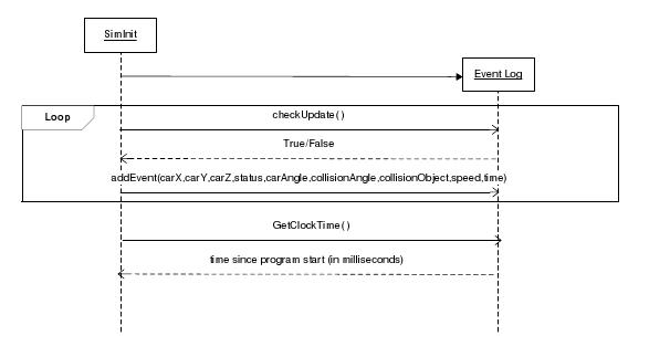
2.3.11 - EventLog
Purpose:
This class holds events created by the driving simulator. It efficiently stores car status data during
run time and generates an XML string when simulation is finished.
Requirements:
This class requires cstdlib, time.h, sstream, and cstring to
run. It also depends on EventNode, but
that definition is included in the same header file.
Code Description:
After creating the new object, the class creates a single linked
list of EventNode classes to hold all data.
Events are meant to be added in 500 millisecond intervals with
extraneous events added as needed. The
EventLog.checkUpdate function allows users to see if 500 milliseconds have
passed since the last update. If that is
the case, this function returns true.
This provides a simple way of checking if an event should be added, then
adding it if necessary through EventLog.addEvent.
The EventLog.addEvent function accepts the car’s position as three
separate float values, the current status code, the car’s angle, the collision
angle and the string of an object it is colliding with if they exist, the car’s
speed, and the current time in milliseconds since the program has started. This function will add an EventNode instance
to the EventLog’s internal linked list.
The EventLog.generateXMLString provides a way to create a human
readable XML string. This string can
then easily be written to any file. The
function uses a string stream to hold the format the data and then returns a
string as a result.
For debugging purposes, a human readable timer in the form of a
character array can be returned by calling EventLog.GetClockTime.
2.3.11.1 - Sequence Diagram
2.3.11.2 – CRC
Class Properties:
clock_t lastUpdate
clock_t currentRunTime
int hr
int min
int sec
EventNode *startEvent
EventNode *lastEvent
Method Prototypes:
EventLog()
char* GetClockTime()
void addEvent(float carPosX, float carPosY, float carPosZ, int
status, float carAngle, float collisionAngle, string collisionObject, float
speed, float time)
bool checkUpdate()
string generateXMLString()
~EventLog()
Inheritance:
None
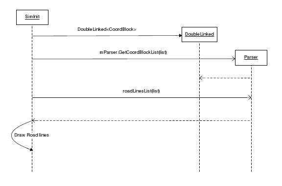
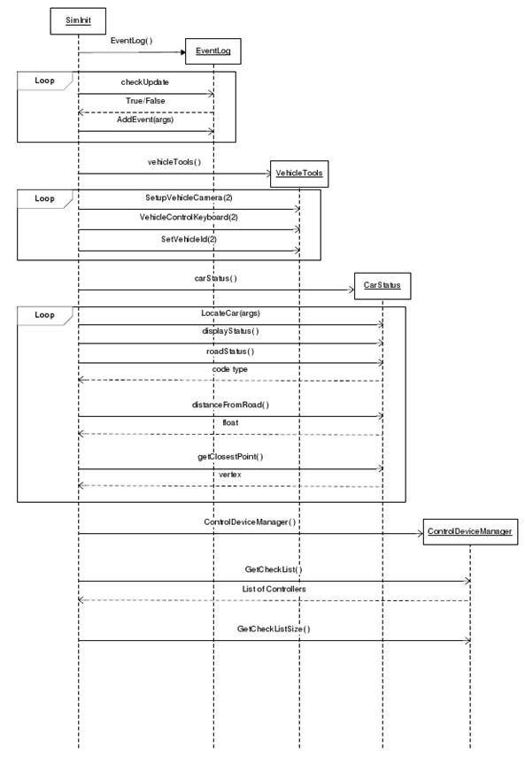
2.3.12 – SimInit
Purpose:
This class contains the main functions for the driving simulator.
It controls crucial operations such as holding the points on the road, logging
the events, handling the movement and alignment of both the car and the camera,
calculating the distance of the car from the center line and creating a status
message based on that, and holding the starting point of the road and car.
Requirements:
Critical requirements for this class to function are all of the
items defined in headers.h.
Code Description:
Simit( ) initialized DarkGDK with the sync rate and type of window
which is borderless in this case, reads points from VectorPionts.txt, and then
opens MemBlock for writing. After
setting up points, it will call DrawIrregularPoly to draw the road. Init( )
draws the basic vehicle cube and positions it to the starting point, creates
the land, and calls code to draw the road, to draw the lines on the road, to
point the camera, and to set the controller. It also prints the welcome message
that is closed by the spacebar, prints status information to the screen, and
adds an event to the log if the appropriate amount of time has passed.
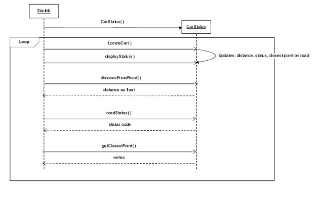
2.3.12.1 - Sequence
Diagram (figure on next page)
2.3.12.2 - CRC
Class Properties:
CoordBlock CoordArrayReal[56];
EventLog evts;
VehicleTools Car;
Vertex3d camera;
CarStatus status;
Vertex3d startPos;
ControlDeviceManager controlManager;
CheckList* controllerList;
char* memblockFileName;
DoubleLinked<CoordBlock> list;
bool displayText;
Method Prototypes:
SimInit()
void Init()
void SimLoop()
void NotesPopup()
void DebugPopup()
void Event Handler()
Inheritance:
None
2.3.13 – CarStatus
Purpose:
This class calculates the cars position from the median of the
road and the car’s status during the execution of the driving simulator. It calculates a code of 0 for Normal Status,
1 for Off Road, 2 for Across the Center Line, and 3 for Collision.
Requirements:
This class requires the Vertex3d class, DarkGDK libraries, and the
math.h header to run.
Code Description:
After creating the new object, the car’s status can be found using
CarStatus.LocateCar() by sending in the arguments of the car’s integer ID, the
road stored as a CoordBlock(), and the number of vertices in the road. This function does a for-loop and uses the
ClosestPointOnSegment() function to find the closest point on each line segment
to the car. The car’s status will be
based on the nearest point on the road.
The function will also calculate which side of the road the car is
on. The status will update based on the
side of the road the car is on and how far away the car is from the median.
CarStatus.distanceFormula() will provide the distance between two
points when given 2 separate Vertex structures.
CarStatus.distanceFromRoad(), CarStatus.roadStatus(), and
CarStatus.getClosestPoint() are public accessors.
For debugging purposes, a human readable output about the car can
be shown by calling CarStatus.displayStatus.
2.3.13.1 - Sequence Diagram
2.3.13.2 – CRC
Class Properties:
float distance
int status
Vertex3d closestPoint
Vertex3d carPos
Method Prototypes:
CarStatus()
void LocateCar(int objectid, CoordBlock roadCoord[], int
arrayLength()
float distanceFromRoad()
int roadStatus()
Vertex3d getClosestPoint()
void displayStatus()
Inheritance:
None
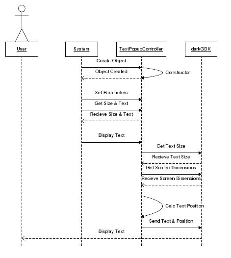
2.3.14 – TextOverlay
Purpose:
There is a need to display text as a 2d overlay for system
information and user messaging. To make the constant usage of text overlay
easier to manage this class maintains a screen position pointer that can be set
for a single block of text permitting other blocks of text to be positioned
relative to the first text without overlap. Auto positioning is enabled by
default but can be disabled to override relative positioning per line of text
if necessary. Offsets and margins can also be set and reset at any time during
the drawing of the text. Animated text can be achieved by adjusting relative
positioning per each draw cycle of the main program loop. This class is
expected to be used within the main drawing loop of a DarkGDK application.
Requirements:
Depends upon DarkGDK.h for access to 2d text control and drawing
Code Description:
This class effects a wrapper around some common 2d text functions
of DarkGDK and adds the ability to write blocks of text using relative
positioning for new lines or for text to be drawn to the right of a previous
line at some offset distance. Currently this is only function for items affixed
to the left margin or to the center of the screen. No options exist for
affixing text to the right margin although the implementation would be subtle
inversion of the calculation for left alignment. These functions are provided
by a single(1) traditional constructor which sets default values to all
properties; Three(3) methods which handle relative positioning and two(2)
overloaded methods to force absolute text position for special circumstances.
Properties are handled with eight(8) accessor methods which can provide text
and cursor position information while allowing the reconfiguration of class
properties during usage.
2.3.14.1 - Sequence Diagram
2.3.14.2 – CRC
Class Properties:
int vertPos
int hzonPos
char* textString
bool autoPos
int fontSize
int newLineSpace
int leftOffsetSpace
double offsetPercent
Method Prototypes:
TextOverlay()
char* GetLastText()
int GetLastPosition()
void SetVertPos(int pos)
void SetNewLineSpace(int space)
void SetOffsetPercent(double percent)
void SetAutoPos(bool autoPos)
void SetFontSize(int size)
void SetLeftOffsetSpace(int size)
void CenterText(char* text)
void LeftOffsetText(char* text)
void CenterText(char* text, int pos)
void LeftOffsetText(char* text, int pos)
void RightofCurrentText(char* text)
Inheritance:
None
2.4 -
Operating Environment
The St
Vincent Driving Simulator is designed to work under windows XP and Vista
compatible computers with a compatible DirectX video adapter.
2.5 -
User Environment
Standard
desktop platforms with a single monitor are supported. This single monitor can
be supplanted with any DirectX compatible video display device, i.e. projector.
2.6 -
Design/Implementation Constraints
At its
current state this simulator is a prototype to prove the viability of DarkGDK
as a platform for a larger simulator application. While external controllers
are generally implemented as proof of concept major operation is done via
keyboard controls. While keyboard use is acceptable during testing the final
application requires sole use of an external control appliance. The software
must also be compatible with simple computer systems that have only basic video
card support.
2.7 -
Assumptions and Dependencies
To allow
for realistic vehicle control it is expected that the user will have a 2-3/4
turn steering wheel controller, and either brake/gas or brake/clutch/gas
controls. Further detail can be obtained from (Section 4.1 - Vehicle).
3 - External Interface Requirements
3.1 -
User interfaces
For the
purposes described in section 2.2.1.1 only the most minimalistic level of
interface is applied to the project. To stay in line with suspension of
disbelief the only direct interface will be that of dash instruments that are
expected within a motor vehicle.
3.2 -
Hardware interfaces
Keyboard
The keyboard is the generic default control for testing the
simulators functions. It has fully implemented control over the simulation
during development and should be maintained as a backup in the event of
external controller failure.
Steering Wheel
This is the target method of interface with the simulator. Due to
the level of user immersion required for the simulators use as a clinical
testing aid. True to live control is required.
3.3 -
Software interfaces
An
external data viewer is included in this project although this interface is via
a data file generated at the end of each simulation.
4 - System Features
4.1 -
Vehicle
4.1.1 - Shape
The shape of the vehicle is of a square in two-dimensional space
and of a cube in three-dimensional space. These two shapes will be created
based on the same given length for the distance between two adjacent points on
the side of either figure.
4.1.2 - Traveling Along Road
The vehicle will be pinned to the surface of the terrain in order
to have the vehicle stay on the terrain and not float off into space. The
z-coordinate of the vehicle and the vehicle’s current position on the terrain
is tracked. To pin the vehicle to the surface of the terrain, the vehicle will
always have the same z-coordinate value as the terrain at each location the
vehicle moves.
4.1.3 - Tracking
Tracking the position and condition of the vehicle is dynamic in
that there is a predetermined polling time for when the position and the
condition of the vehicle is recorded throughout the simulation. According to
these recordings, reports can be generated about significant events and the
overall performance during the simulation.
4.1.3.1 - Car Object Center
Position of the vehicle will be determined by a point at the
center of the vehicle. The point at the center of the vehicle is calculated by
drawing a diagonal from two opposite corners in the square and placing the
center point at the midpoint of the drawn diagonal.
4.1.3.2 - Driving Line
A margin distance will be determined and used to give the lane of
best driving a section along its two parallel outer edges. If the vehicle
enters this marginal area, then an event will be generated. The purpose of this
event is to indicate when the vehicle almost went off the road or into the
other lane. While the importance of this event is not as significant as
actually going off the road or into the other lane, it has an underlying
importance of indicating the details of how well the vehicle is being driven
within the lane of best driving.
To determine whether the vehicle is in the best driving lane, in
the oncoming traffic driving lane, or off the road, a perpendicular line from
the road vector line of a given length is created using normals. The vehicle is
one end point on this perpendicular line. Based on the location of the opposite
end point of the perpendicular line, the relative position of the vehicle can
be determined at any given time.
Deviation
Using the vector that created the road surface, another vector can
be formed for determining the center of the best driving lane by shifting the
original vector. This vector that determines the center of the best driving
lane can be compared to the vehicle vector to calculate the deviation from the
center of lane. Thus, the center of the lane vector lays out the best possible
path for the vehicle to travel during the simulation. Comparisons between these
two vectors will be made according to a specified time interval and the
deviation of the vehicle’s vector will be recorded. An additional benefit from
this center of the lane vector is that whenever it is found that the vehicle is
in the wrong lane or off the road, the center of the lane vector can be used to
calculate how far the vehicle has traveled away from its appropriate position
in the best driving lane.
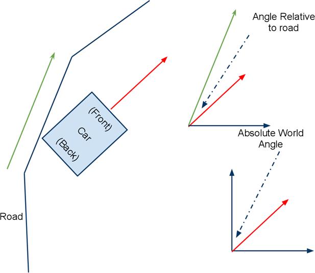
4.1.3.3 - Car Angle
Relative
Along with the center point of the vehicle that determines the
position of the vehicle at any given time, there will be two other points
attached to the vehicle, one at the front and one at the back of the vehicle.
These two points will be used to calculate a vector which can be used to
determine the angle or direction of the vehicle on the terrain. To find the
relative vehicle angle, compare the vector of the vehicle against the slope of
the closest road segment. To find the absolute vehicle angle, compare the
vector of the vehicle against the x- and y-coordinate axes of the terrain.
Absolute
This angle is provided directly by DarkGDK
Figure
4.1.3.4 - Collision/Bounding
Road Lines
The vehicle will have four points indicating the vehicle’s edges
on each side. These four points will be located on the four corners of the
vehicle. The purpose of these points is in future implementations to indicate
if any part of the vehicle collided with another object. This is significant
because the current method uses only the center point of the vehicle which
could overlook pertinent collision events.
Repositioning
If the vehicle experiences a severe collision or a collision where
moving afterwards is impossible, the vehicle will be reposition onto the road.
The repositioning will be to the center of the driving lane across from the
area of the collision. If the collision is extremely severe, say colliding with
another vehicle head on, the simulation ends to replicate reality since after
such a collision the vehicle would be totaled and not drivable. If the vehicle moves in the opposite
direction necessary to complete the simulation for an “x” amount of time, then
the vehicle will be repositioned to face the correct direction in the center of
the driving lane across from the last recorded position of the vehicle. If the
vehicle would happen to go the wrong direction and approach the vehicle’s
starting position, once the vehicle reached the starting position, the vehicle
would be stopped and repositioned to face the correct direction at the starting
position. If the vehicle ventured of the road and into the terrain for an “x”
amount of time, then the vehicle would be repositioned to the center of the
best driving lane across from the last recorded position of the vehicle on the
terrain. Repositioning should be more or less infrequent and the result of
great misbehavior on the drivers part because reposition is not realistic. The
time “x” mentioned above should be a long period of time in order to eliminate
minor mistakes from triggering repositioning and to leave only blatant
misbehavior by the driver to cause repositioning. Also if the terrain contains
non-drivable areas such as bodies of water or cliffs and the vehicle drives
into these areas, the vehicle will be repositioned as before to the best
driving lane across from the last position recorded on the drivable terrain.
4.1.3.5 - Collidable Object Proximity
All objects that have the potential of being collided into have a
sensorial field surrounding them of a given radius. The purpose of this
sensorial field is that if the vehicle ever enters this field a collision event
is generated and recorded. It is important to set a reasonable sized radius for
the sensorial field of objects because if the field is too small or large,
events would be left out or unnecessarily generated. This sensorial field will
be generated by drawing an invisible circle on the terrain around the
collidable object according to the specified radius. This area on the terrain
will be checked on a specified time interval to see if the vehicle has entered
the area.
4.1.3.6 - Criteria
Distance
Calculate the distance the vehicle has traveled by after each time
interval when the position of the vehicle is recorded use the distance formula
to determine the distance between the newly recorded position and the next to
last position recorded. The vehicle’s distance will be stored globally for use
throughout the program. This distance value will begin at zero at the start of
the simulation and as the vehicle moves, the incremental distances calculated
after each time interval will be added to global distance value. The distance
value is always positive even if the vehicle moves backwards.
Speed
Calculate the speed of the vehicle based on the distance traveled
and the elapsed time. To complete this calculation use the vehicle’s distance
value and simulation’s clock. The speed of the vehicle is recorded after the
given time interval when the position of the vehicle is updated and recorded.
Speed Change
Apply deceleration to the vehicle when going up an incline and
acceleration to the vehicle when going down an incline. The rate of
acceleration and deceleration will be determined based upon the calculation of
the angle between the directional vector of the vehicle and a level line on the
terrain. Acceleration and deceleration can be distinguished between based upon
the location of the directional vector when placing the directional vector in a
two-dimensional graph with the directional vector point at the back of the
vehicle at the origin. If the direction vector is graphed in the first or
second quadrants, then deceleration will be applied to the vehicle. If the
directional vector is graphed in the third or fourth quadrants, then
acceleration will be applied to the vehicle.
Acceleration
When the vehicle is at rest, allow the vehicle to accelerate to
have a drivable speed. Have a max speed that the vehicle cannot exceed in order
to avoid continuous acceleration and thus extreme speeds. This can be
accomplished with a checking of the condition of the vehicle: if the vehicle is
at rest, allow the vehicle to accelerate; or if the vehicle is at a speed below
the maximum speed allowed, allow the vehicle to accelerate. The rate of
acceleration should be dependent on the level at which the accelerator is being
pressed in at a given moment.
Deceleration
When the vehicle is in motion, allow the vehicle to decelerate to
a stop instead of coming to a drastic stop in the mist of just moving or
continuing at a constant speed. This can be accomplished with a checking of the
condition of the vehicle: if the vehicle is in motion and if the breaks are
being hit, allow the vehicle to decelerate; or if the vehicle is in motion and
if neither the accelerator nor break are being pressed, allow the vehicle to
decelerate; or if the accelerator and the break are being pressed simultaneously
but the break is being pressed in more so than the accelerator, allow the
vehicle to decelerate. The deceleration of the vehicle whenever the break is
pressed should be the greatest of the decelerations. The rate of deceleration
of the vehicle when dependent on the break should be calculated based on the
level at which the break is being pressed in at a given moment. The
deceleration of the vehicle whenever neither petal is pushed should be a slight
deceleration to allow the vehicle to roll to a stop gently. The most complicated deceleration will be
when both petals are being pressed. In this case the rate of deceleration
provided by the pressing of the brake is subtracted from the rate of
acceleration provided by the pressing of the accelerator. (Reminder: The rate
of deceleration is a positive value in this instance.)
4.1.4 - Turning Angle and Rate
The turning of the vehicle will be determined by taking into
consideration the pivot point of the vehicle and the steering rotational input
from the steering wheel controller to provide a realistic turn.
Calculation
As speed increase, the turning radius of the vehicle will
decrease. Thus when the vehicle is driven as high speeds, making sharp turns
will not be possible as in reality. Calculating this decrease of turning radius
involves taking fractions of the turning radius established as the base turning
radius for slow speeds. Once the vehicle’s speed exceeds the threshold for slow
speeds, fractions will be multiplied to the base turning radius to provide the
new turning radius. The fractions are determined by calculating the numerator
as the maximum speed minus the current speed and the denominator as the maximum
speed.
4.1.4 - Steering
Pivoting
To
give the driving of the vehicle a more realistic feeling, the vehicle will
pivot around the center of the back wheels (or toward the back of the vehicle)
when turning.
Interface
A camera is attached to the vehicle so that the camera is
positioned inside the vehicle at the approximate position that the driver would
be seated. This means the camera should be position toward the left side of the
vehicle and about three feet from the windshield. In the camera’s view there
should be the windshield, the dashboard with rudimentary gages, and a slight
view of the hood of the vehicle. The main measurement that the gages should
display are the speed of the vehicle and time elapsed driving in the
simulation, like a clock on the dashboard but instead of a clock it is a timer.
In addition, the dashboard should also have a signal that displays informing
the driver when a collision has occurred. This signal will be beneficial to the
driver whenever a collision occurs that is not head on or toward the front of
the vehicle. All of this information will encompass the basic interface seen on
the screen during the driving simulation.
4.2 - Environment
4.2.1 - Ground
4.2.1.1 - Road Surface Matching
Ground beyond the road surface is created by texturing a height
map. In the current implementation of the project this surface has a height
value set to but independent of the road height. To make this height map match
the road surface it is necessary to seek out the closest point to the road edge
that corresponds to the height of the road. Once this point is located it can
be set to the height of the road. The general rule is that no change in height
can be more than 20 degrees from the last 3 road sections. By avoiding huge
rapid changes in terrain the likelihood of there being difficulty matching
terrain height should be minimized.
Terrain Depth
To provide a smaller margin for error when matching terrain to the
road height a minimum depth of the terrain height map is double the number of
segments of the road over the same distance of the road. Thus, if the road has
a width of 100 units and 5 road segments within that width, each segment must
account for at least 20 units of distance thus the height maps width must have
10 segments per 100 width thus permitting 10 units of distance per terrain
segment. The same will be true for the length of the road along the other axis.
This will not be an absolutely accurate mechanism for calculating road segments
because it does not incorporate the amount of segment length lost from varied
height and turns. This will not be much concern since none of the road segments
or terrain points will match up correctly exactly.
Finding Road Dimensions
To calculate the segment bounds of the road surface the mesh must
be disassembled to find the max and min of each cardinal direction. From these
points the rectangular bounds of the region is possible.
4.2.1.2 - Infinite Terrain
Outside the range of the height map planes will be tiled from to
create a simple to draw series of regions which will be "infinite" in
distance. By "infinite" the dimensions will be of such a size as to
make it improbable for a user to reach the end without being completely outside
the bounds of expected testing.
4.2.2 - Skybox/Skysphere
The skybox and skysphere is the effective horizon that sits at an
infinite distance from the camera. This permits the usage of multiple backgrounds
to represent multiple environments.
4.3 -
Road
4.3.1 - Road Creation
4.3.1.1 - Generation of Road Path
Static Vector(i)
Vector Creation
To create a static vector that will not create polygons that
overlap the distance between each adjacent set of points must be greater than
or equal to the distance defined for the distance of the normal point from the
line define by the two adjacent points from the original point. The process to
easily create these points by hand is to draw a circle whose center is any
point and whose radius is the set distance between points. Thus by selecting
any point on the circle the distance will be correct.
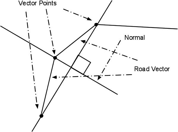
Normal Calculation
The calculation will take in 3 sequential vector points. With a
line drawn from the first and last points of the 3 we can find an estimated
normal of the middle point. by using this slope of the normal we can plot a new
point to the right and left of the middle point. These normal points become the
basis for a polygon on each side of the initial vector line.
Vector Drawing Tool
While creating of a vector by hand is not a complex process. For
testing there needs to be a program to generate a point at a static distance
from another point at any angle. From this tool a compatible vector list will
be output ready for testing.
4.3.1.2 - Generation of Road Mesh(i)
The surface that is to be displayed as the visual road will be
generated by expanding a single vector into a series of polygons. This will
permit variations in direction and in height when implemented. This surface
will be created as a single mesh from a single vector or a composite of similar
smaller meshes. Goals behind road generation are to permit the storage of
absolute positioning within the object itself. At any time a mesh may be
positioned and its bounds can be extracted.
Creating MemBlock(i)
MemBlocks are a binary access data storage method that allows a
block of physical memory to be directly written to and read from active memory.
While the process does not actually allow for manipulation of active memory the
effect is the same. Through the use of DarkGDK it is possible to create MemBlocks
of binary files used by the DirectX renderer DirectDraw. Once created a MemBlock
may also be saved to a binary file for later use. Through this process once a
road is generated it does not have to be regenerated each time while allowing
for persistence of original vector information by reading and reorganizing the
data from a MemBlock.
Drawing Mesh(i)
The DirectX renderer, Direct Draw permits the drawing of
sequential points to form a mesh. In these circumstances draw order is very
specific. From any point the next successive point must be drawn to the right
of the last. This is the result of positive angles are calculated from the left
side in a clockwise direction towards the next line segment. If an angle is negative
or turns to the left from the previous point then the line is culled.
In the process used to draw sequential polygons it is imperative
to start from the smallest primitive to be drawn, the triangle. From this a
larger polygon is constructed. In the case of road generation the maximum unit
is a 4 sided polygon repeated. This drawing order is specific to the direction
and relative angle of the road segment.
Flexible Vertex Format
This format is not DirectX specific but does allow DirectX renders
to read point information and maintain vertex information including normal
values, uv coordinates, and diffuse color.
Example of FVF 338 in Dark GDK
Please see Section 2.3.5 – DrawIrregularPoly
Advice
about data types
When
writing or reading a MemBlock the position is relative to 1 byte each position
that you can access is 1byte so a Dword or Double word is the same length as an
uint32 (32 bit unsigned integer). Thus to not overwrite data within the MemBlock
it is necessary to allow for the right amount of space before proceeding.
As in the example below each line movies the MemBlock position by 4 bytes or 32
bits. The smallest amount of information is 1byte and the largest is a Dword.
Advice
about MemBlock sizes. This is easy to derive mathematically. For a 338 by 36
bit vertex FVF we can calculate the size of the MemBlock by taking the header
which is
[96bit
+ ( Number of Vertices x ( 3 x 96bit)] / 8bit
The
break down is that the header is 96 bit and each vertex coordinate, normals coordinate,
and diffuse color / uv coordinate is 96 bit each so we have 288bits for each
vertex multiplied by the number of vertices plus the header. Now we have the
raw bits of the MemBlock divide by 8 to get the number of bytes.
Code
to Generate above MemBlock
This
MemBlock will create the same thing that dbMakeObjectPlain(1,10,10);
Of
course this method allows up to make irregular planes. I will write a class
around this to make created the planes as easy as giving 4 coordinates.
a
= 0;
//Custom Mesh Dynamically
//Header
dbMakeMemblock(2,
228);
dbWriteMemblockDword(2,a=a,338);
dbWriteMemblockDword(2,a=a+4,36);
dbWriteMemblockDword(2,a=a+4,6);
//First Cord
dbWriteMemblockFloat(2,a=a+4,5);
dbWriteMemblockFloat(2,a=a+4,5);
dbWriteMemblockFloat(2,a=a+4,0);
// Normals
dbWriteMemblockFloat(2,a=a+4,5);
dbWriteMemblockFloat(2,a=a+4,5);
dbWriteMemblockFloat(2,a=a+4,0);
//Difusion Color
dbWriteMemblockDword(2,a=a+4,1065353216);
//UV Cords
dbWriteMemblockFloat(2,a=a+4,0);
dbWriteMemblockFloat(2,a=a+4,5);
//Second Cords
dbWriteMemblockFloat(2,a=a+4,-2);
dbWriteMemblockFloat(2,a=a+4,-5);
dbWriteMemblockFloat(2,a=a+4,0);
// Normals
dbWriteMemblockFloat(2,a=a+4,-5);
dbWriteMemblockFloat(2,a=a+4,-5);
dbWriteMemblockFloat(2,a=a+4,0);
//Difusion Color
dbWriteMemblockDword(2,a=a+4,1065353216);
//UV Cords
dbWriteMemblockFloat(2,a=a+4,0);
dbWriteMemblockFloat(2,a=a+4,-5);
//Third Cords
dbWriteMemblockFloat(2,a=a+4,-5);
dbWriteMemblockFloat(2,a=a+4,5);
dbWriteMemblockFloat(2,a=a+4,0);
// Normals
dbWriteMemblockFloat(2,a=a+4,-5);
dbWriteMemblockFloat(2,a=a+4,5);
dbWriteMemblockFloat(2,a=a+4,0);
//Difusion Color
dbWriteMemblockDword(2,a=a+4,1065353216);
//UV Cords
dbWriteMemblockFloat(2,a=a+4,0);
dbWriteMemblockFloat(2,a=a+4,-5);
//Fourth Cords
dbWriteMemblockFloat(2,a=a+4,5);
dbWriteMemblockFloat(2,a=a+4,5);
dbWriteMemblockFloat(2,a=a+4,0);
// Normals
dbWriteMemblockFloat(2,a=a+4,5);
dbWriteMemblockFloat(2,a=a+4,5);
dbWriteMemblockFloat(2,a=a+4,0);
//Difusion Color
dbWriteMemblockDword(2,a=a+4,1065353216);
//UV Cords
dbWriteMemblockFloat(2,a=a+4,0);
dbWriteMemblockFloat(2,a=a+4,5);
//Fifth Cords
dbWriteMemblockFloat(2,a=a+4,5);
dbWriteMemblockFloat(2,a=a+4,-5);
dbWriteMemblockFloat(2,a=a+4,0);
// Normals
dbWriteMemblockFloat(2,a=a+4,5);
dbWriteMemblockFloat(2,a=a+4,-5);
dbWriteMemblockFloat(2,a=a+4,0);
//Difusion Color
dbWriteMemblockDword(2,a=a+4,1065353216);
//UV Cords
dbWriteMemblockFloat(2,a=a+4,0);
dbWriteMemblockFloat(2,a=a+4,-5);
//Sixth Cords
dbWriteMemblockFloat(2,a=a+4,-5);
dbWriteMemblockFloat(2,a=a+4,-5);
dbWriteMemblockFloat(2,a=a+4,0);
// Normals
dbWriteMemblockFloat(2,a=a+4,-5);
dbWriteMemblockFloat(2,a=a+4,-5);
dbWriteMemblockFloat(2,a=a+4,0);
//Difusion Color
dbWriteMemblockDword(2,a=a+4,1065353216);
//UV Cords
dbWriteMemblockFloat(2,a=a+4,0);
dbWriteMemblockFloat(2,a=a+4,-5);
Drawing Complex Objects
For the current system to create a road surface a single linear
vector must be defined but this does not permit the rendering of complex road
surfaces like intersections or Y's in the road. The current linear drawing
method can be adapted to support complex and branched surfaces. The current
method draws the right side of the road surface and then the left side of the
road surface. This can be applied if the drawing can track the right side of a
complex vector by identifying an additional point at each dead end.
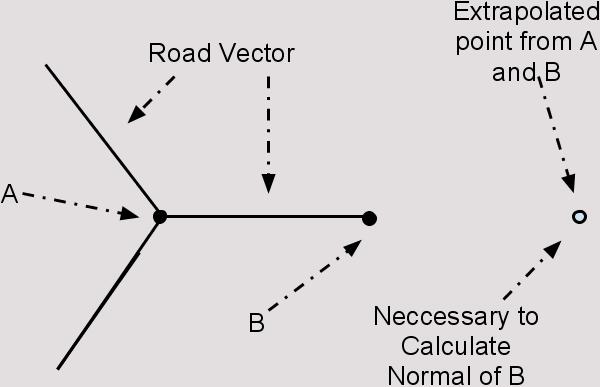
In this figure we see what the system would have to account for
when it reached a dead end.
In the case of a loop it is necessary to detect if a polygon
already exists within the range of the normal distance to the next set of
points. This will assure that system does not redraw overtop of already drawn
surface areas.
Saving Mesh(i)
By considering meshes as synonymous with MemBlocks to save a mesh
using DarkGDK consists of converting it to a MemBlock and then saving that MemBlock
to a file. Although this file is not human readable it can be directly loaded
back into the environment at any time.
Mesh Manipulation
Since meshes and MemBlocks are synonymous we can treat a mesh as
sequenced data in a MemBlock. Currently implemented is a MemBlock parser which
will return the sequential data of the MemBlock. This data is a series of
Coordblocks which contains all of the vertex data, normals, and diffuse
information about the object. To manipulate a mesh by moving it we can affect a
change in xyz distance across all points and the resulting MemBlock will be
shifted by those values when redrawn. The same is true for sequential growth in
height across the surface. If a surface's coordinates are extracted and
manipulated lateral tilts can also be created.
Mesh Parsing
4.3.1.3 - Bounding and Collision
Bounding by Distance Calculation(i)
While bounding by collision is possible using the same mechanism
used by road and road line generation to create regions about the road surface
as a single object for collision tracking, but since bounding is being managed
based upon a simple range from the road surface this is not needed.
4.3.1.4 - Texturing
Road Lines
While the road surface is a complex object which contains
texturable uv information it is easier to take the same road information to
generate additional object segments that represent the road lines both yellow
and white on the road. In the future these additional road line objects can be
used to better validate the vehicles position on the road and provide enhanced
collision detection.
4.4 -
Events
4.4.1 - Data
4.4.1.1 - Static
Start Position
Timing
Start
The starting time of the event will be based off of when the
simulation starts. For example, the
event will start 20 seconds from the start of the simulation.
Stop
The stopping time of the event will be relative to the starting
time. For example, one may only last
until 25 seconds and will then go out of sight.
Result
The result of an event will depend on the type of event. If the car hits a tree, then it will display
that it has crashed and the car will reset on the road. If the car hits an object such as a
pedestrian, then the car will not come to a complete stop like when striking a
tree, it will keep moving.
4.4.1.2 - Dynamic
Event Trigger
Location Triggered
After the car reaches a certain point on the road, it will trigger
an event or sequences of events.
Event that Triggered
Depending on prior events, new events or event sequences will be
created.
Timing
Start
Starting time will be either immediate after a location or event
trigger or it will start a certain time after.
Stop
Stopping time varies per event and will be relative to the
starting time.
Result
The result of an event will depend on the type of event. If the car hits a tree, then it will display
that it has crashed and the car will reset on the road. If the car hits an object such as a
pedestrian, then the car will not come to a complete stop like when striking a
tree, it will keep moving.
4.4.2 - Event Sequencing
4.4.2.1 - Predefined Event Sequence
Once the car reaches a certain point on the road, it may trigger
an event sequence such as the proceeding example. Ball on road 20 feet ahead and the event will
be triggered when the bounding box of the car collides with the bounding box of
the ball, pedestrian walks across road 200 feet ahead and the event will be
triggered when the bounding box of the car collides with the bounding box of
the pedestrian, car in current lane 300 feet ahead and the event will be
triggered when the bounding box of the car collides with the bounding box of
the other car, car in opposite lane 400 feet ahead and the event will be
triggered when the bounding box of the car collides with the bounding box of
the other car, and car in opposite lane 450 feet ahead and the event will be
triggered when the bounding box of the car collides with the bounding box of
the other car.
4.4.2.2 - Random Event Sequences
To keep the test studies more accurate, a random event sequence generator
may be included. This random sequence
will ensure duplicate participants will not have a better chance of driving
without error on the simulator. It will
also ensure that previous participants cannot tell others about when events
will occur.
4.4.3 - Simultaneous Events
Events occurring at the same time will need to be accounted
for. For example, the event that a car
is off of the road and the event that a car has struck a tree will be
simultaneously occurring. These will be
reported in the order of what has been previously occurring. In this case, the event off the road will be
reported first and then the event that the car has struck an object,
specifically a tree, will be reported immediately following. If they occur precisely at the same time,
then the extraneous event gets precedence.
4.4.4 - Event Types
0 - Normal
1 - Off Road
2 - Cross Center Line
3 - Collision with Object
~ - Vehicle Reset
~ - Reaction Status
4.5 -
Collision
4.5.1 - Driving
4.5.1.1 - Tracking Event Sequence
The collision is recorded.
The collision event can occur with any angle of the vehicle.
The speed and angle of the vehicle at the time of the collision
will be recorded. The data that is
recorded will be used to determine the severity of the collision with the
object.
4.5.1.2 - Collision Data
4.5.2 - Collision Tracking
Location
During the simulation there will be a list of event types of the
vehicle that can be viewed in section events->list of event types. The location will be recorded by using a flag
to place at the spot of the collision and will be outputted to see after the
simulator is done. If a collision with
an object occurs out of the designated driving lane for the vehicle, that event
will be recorded first followed by a record of the collision with the object.
Speed
The speed of the vehicle at the time of the collision will also be
recorded. The speed of the vehicle is
visible at the top of the screen during the simulator so the user will know the
current speed at all times. As soon as
the vehicle collides with another object, the current speed of the vehicle at
the time of impact will be recorded and placed in the output.
Angle
The angle of the vehicle during the collision will be documented
using the record of the last recorded vector vs. the horizon of the object that
it collided with. The angle and speed of
a collision determine the severity of the collision. If the angle of the collision with an object
creates enough damage that the vehicle is not drivable, the vehicle will be
repositioned on the road in the correct lane.
The main collisions that would prevent the vehicle from being drivable
would be: a collision to the left or right front of the vehicle which would
ruin one of the tires or a collision head on that would ruin the engine. The simulation will continue as long as the
vehicle is still drivable.
Duration
Some collisions may last longer than others, so the duration of
the collision will also be recorded.
Severe collisions with the vehicle may only take a second depending on
the damage of the vehicle. If the
vehicle is not drivable, it will be immediately placed back on the road. If the collision is not so severe, the time
that the vehicle is colliding with another object will be recorded. If the collision is very severe, the
simulation will end to replicate reality.
Please see section vehicle->repositioning.
4.5.3 - Repositioning
If the vehicle experiences a severe collision or a collision where
moving afterwards is impossible, the vehicle will be reposition onto the road. The repositioning will be to the center of
the right driving lane across from the area of the collision. If the collision is extremely severe, for
example, colliding with another vehicle head on, the simulation ends to
replicate reality since after such a collision the vehicle would be totaled and
not drivable.
4.5.4 - Reporting Results
All of the collisions will be recorded and placed into an output
document. There will be a list of all
the collisions that occurred during the simulation, along with the all the
factors contributed to the collision. In
the document, there will be a record stating if the collision occurred at an
event or at a random place on the course.
4.6 -
Data Management
The
information under these subheadings is important pieces of information that
apply to the project. The first
subheading includes data that should be eventually stored in the project. Currently the event log class does not keep
this information, but it will be smart to have in later iterations. The second subheading includes information
that is currently handled and stored by the event log.
4.6.1 - Data Classification
The information under these subheadings is important pieces of
information that apply to the project.
The first subheading includes data that should be eventually stored in
the project. Currently the event log
class does not keep this information, but it will be smart to the have in later
iterations. The second subheading
includes information that is currently handled and stored by the event log.
4.6.1.1 - Test Criteria
Participant Name
Overseer Name
Group
Sequence
Number
Date
4.6.1.2 - Simulation Criteria
Start Time
The start time in milliseconds will be the time of the first event
in the event log. This is tracked by the
milliseconds since the program started.
End Time
The end time in milliseconds will be the time of the last event in
the event log. This is tracked by the
milliseconds since the program started.
Vehicle Status
Position
The vehicle’s position, calculated from the global coordinates,
will give us information about the car in relation to the road. This is another necessity to generate any
meaningful reports.
Relative to Road Center
Relative to Start and End
Angle
Relative to Colliding Object
By taking the difference between the car’s global angle and the
colliding object’s global angle, the severity of the crash may be
estimated. An example graph is included
below. Some angles may need to be
regulated by adding or subtracting 90 until a value between 0 and 90 is reached.
Global
The vehicle’s angle is an important piece of data to see if the
car is going the correct direction on the road.
This is tracked by the object’s stored global angle.
Speed
Another important part about the car is the current speed it is
traveling. It is calculated by the
amount of displacement the car moves each cycle.
Distance from Center Line
The distance from the center line is calculated using a function
to find the nearest point on the road compared to the car and then using the distance
formula.
4.6.2 - Data Storage
During the simulation, the data is stored in an event log class
that is a linked list of event nodes.
Each node holds the needed information.
4.6.2.1 - XML
At the end of simulation, the event log class has the ability to
generate an XML data string.
4.6.2.2 - Aggregation Rate
Event data will be added every half second as long as the vehicle
does not collide with any objects. As we implement collisions, we can allow the
collision event to add extra event data to our log.
Data Growth Rate
Report Size
The current XML document allows the storage of approximately one
thousand events in a one megabyte file.
This allows 8 minutes of data to be tracked in a one megabyte file.
4.7 -
Reports
4.7.1 - During Simulation
When the program begins, in the center of the screen, instructions
on how to use the program are displayed.
Pressing the spacebar will clear out the message. The message informs the user that the arrow
keys control the vehicle, the return key resets the vehicle’s position, and the
tab key shows debug information.
4.7.1.1 - Real Time Reporting
On the upper left of the screen, during program execution,
information is displayed. The vehicle
id, the vehicle’s xyz coordinates, the vehicle’s angle, the velocity of the
vehicle, the running time of the program, and the car’s relative position to
the road.
Relative Distance from Road Center
The car’s position on the road is displayed in the upper left-hand
corner of the screen. This message
displays if the user is in the correct lane, the wrong lane, or if the user is
off the road. Also, the distance the
user is from the center line is displayed.
4.7.1.2 - End User Instructions
When the program begins, in the center of the screen, instructions
on how to use the program are displayed.
Pressing the spacebar will clear out the message. The message informs the user that the arrow
keys control the vehicle, the return key resets the vehicle’s position, and the
tab key shows debug information.
4.7.2 - Post Simulation
4.7.2.1 - Format
As the program is running, it will be compiling statistics on the
user’s driving that will be outputting as XML at the end of program
execution. Items that will be recorded
are the vehicle’s position, speed, status, angle, collisions, and the times
that these events occurred. This
information about the vehicle will be reported in 1 second intervals.
4.7.2.2 - Graphs
After program execution, a graph will be created showing the user
their deviation from the best driving line.
The x-axis will represent the time and the y-axis will represent the
deviation. In the center of the y-axis
will be 0, which is the best driving line.
Positive y values will represent deviations to the left while negative y
values will represent deviations to the right.
At times when there are obstacles to avoid, those periods of time will
be highlighted on the graph so the user will know if they attempted to steer
away from an impending collision.
Example
4.7.2.3 - Summary Report
After the graph is created, a summary report of the information
displayed on the graph will be created.
This report will include the events, the average deviation, the max
deviation, the distances from the events, collisions, and the time spent in the
wrong lane and off road.
Example
4.7.2.4 - Collision Report
A collision report will be generated after program execution. This report will list all events that
occurred that the user would need to adjust their driving trajectory to avoid a
collision. The times of these events
will be listed as well as if the user avoided the collision. If the user did collide with the object, the
speed and angle of collision will be recorded and displayed.
Example
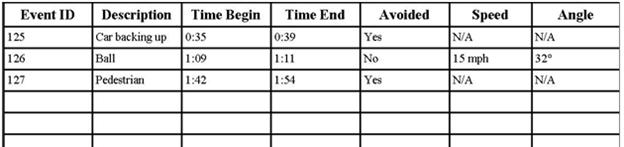
5 - Other Requirements
5.1
Performance requirements
Dark GDK requires
Microsoft's Visual C++ 2008 Express compiler.
Minimum:
Pentium
III 1GHz or equivalent
Windows
XP (Home/Pro) / Vista
1 GB of
hard disk space
512 MB of
Ram
Fully
DirectX compatible Graphics Card with 128 MB Memory or more and Hardware 3D
Acceleration
DirectX
compatible Sound Card
We
recommend your video card has at least 256 MB of memory to get the most from
the Dark GDK. You will otherwise be limited in the size of game and type of
effects you can use. Certain features of the Dark GDK (such as vertex / pixel
shaders) require a suitably powerful graphics card. Please check with your
video card manufacturer before purchasing.
Recommended
Dual Core
1.8GHz or above
Windows
XP (Home/Pro) / Vista
1 GB of
hard disk space
1 GB of
Ram
Fully
DirectX compatible Graphics Card with 256 MB Memory or more and Hardware 3D
Acceleration
Direct X
compatible Sound Card
5.2
Safety requirements
Photosensitive Seizure Warning
A very small percentage of people may experience a seizure when
exposed to certain visual images, including flashing lights or patterns that
may appear in video games. Even people who have no history of seizures or
epilepsy may have an undiagnosed condition that can cause these
"photosensitive epileptic seizures" while watching video games.
These seizures may have a variety of symptoms, including
lightheadedness, altered vision, eye or face twitching, jerking or shaking of
arms or legs, disorientation, confusion, or momentary loss of awareness.
Seizures may also cause loss of consciousness or convulsions that can lead to
injury from falling down or striking nearby objects.
Immediately stop playing and consult a doctor if you experience
any of these symptoms. Parents should watch for or ask their children about the
above symptoms - children and teenagers are more likely than adults to
experience these seizures.
The risk of photosensitive epileptic seizures may be reduced by
taking the following precautions:
* Play in a well-lit
room
* Do not play when you
are drowsy or fatigued
If you or any of your relatives have a history of seizures or
epilepsy, consult a doctor before playing.
6 - Appendix
6.1 - Appendix
A: Terminology/Glossary/Definitions list
collision. the act of (a) vertex(s) passing through the
space defined by the vertexes of another object.
collision
box. Bounding Box - defined region of
space that generally has no visible components but can be collided with.
object
culling. Making an object's mesh and
its texture not visible. Generally a culled object may still have a physical
effect on other objects
object. The combination of vertices to create a mesh
that can be drawn into a visible entity within a 3D environment.
camera. The Field of View within a 3D environment
sky
box. A standard cube object that is
drawn inverted as to allow for the inside of the cube to be visible. This cube
also exists at an "infinite" relative distance from the camera.
mesh. The set of vertices, UV Coordinates, and
Normals Coordinates that make up an object.
texture. A bicubic image wrapped around a wireframe
object with relative position matched to the uv coordinates defined by.
uv. Static per vertex coordinates for mapping
distance between texture points.
normal.math. Perpendicular point to a line generally in 2
dimensions.
normal.textures. Perpendicular point to a surface generally
in 3 dimensions
MemBlock. Raw binary representation of an object i.e.
a mesh
vertex. Set of spatial coordinated representing the
location of a point within the 3D environment.
draw
order. In different 3D systems this can
vary but it defines in which direction an object must be drawn for it to be
visible. Generally a mesh only shows 1 face all other faces are
transparent.
e.g. A Triangle has a top face and an underside face. Depending on the order
the vertices are aligned defines which face is textured.
vector.data
structure. An arbitrary sized array
data storage structure implemented in the C++ STL.
vector.usage. A linear list of 3 dimensional points that
are used to define the height and direction of a linear surface.
6.2 - Appendix
B: License
Creative
Commons Attribution-Share Alike 3.0 United States
CREATIVE
COMMONS CORPORATION IS NOT A LAW FIRM AND DOES NOT PROVIDE LEGAL SERVICES.
DISTRIBUTION OF THIS LICENSE DOES NOT CREATE AN ATTORNEY-CLIENT RELATIONSHIP.
CREATIVE COMMONS PROVIDES THIS INFORMATION ON AN "AS-IS" BASIS.
CREATIVE COMMONS MAKES NO WARRANTIES REGARDING THE INFORMATION PROVIDED, AND
DISCLAIMS LIABILITY FOR DAMAGES RESULTING FROM ITS USE.
License
THE WORK
(AS DEFINED BELOW) IS PROVIDED UNDER THE TERMS OF THIS CREATIVE COMMONS PUBLIC
LICENSE ("CCPL" OR "LICENSE"). THE WORK IS PROTECTED BY COPYRIGHT
AND/OR OTHER APPLICABLE LAW. ANY USE OF THE WORK OTHER THAN AS AUTHORIZED UNDER
THIS LICENSE OR COPYRIGHT LAW IS PROHIBITED.
BY
EXERCISING ANY RIGHTS TO THE WORK PROVIDED HERE, YOU ACCEPT AND AGREE TO BE
BOUND BY THE TERMS OF THIS LICENSE. TO THE EXTENT THIS LICENSE MAY BE
CONSIDERED TO BE A CONTRACT, THE LICENSOR GRANTS YOU THE RIGHTS CONTAINED HERE
IN CONSIDERATION OF YOUR ACCEPTANCE OF SUCH TERMS AND CONDITIONS.
1.
Definitions
"Collective
Work" means a work, such as a periodical issue, anthology or encyclopedia,
in which the Work in its entirety in unmodified form, along with one or more
other contributions, constituting separate and independent works in themselves,
are assembled into a collective whole. A work that constitutes a Collective Work
will not be considered a Derivative Work (as defined below) for the purposes of
this License.
"Creative
Commons Compatible License" means a license that is listed at http://creativecommons.org/compatiblelicenses that has been approved by Creative Commons as being
essentially equivalent to this License, including, at a minimum, because that
license: (i) contains terms that have the same purpose, meaning and effect as
the License Elements of this License; and, (ii) explicitly permits the
relicensing of derivatives of works made available under that license under
this License or either a Creative Commons unported license or a Creative
Commons jurisdiction license with the same License Elements as this License.
"Derivative
Work" means a work based upon the Work or upon the Work and other
pre-existing works, such as a translation, musical arrangement, dramatization,
fictionalization, motion picture version, sound recording, art reproduction,
abridgment, condensation, or any other form in which the Work may be recast,
transformed, or adapted, except that a work that constitutes a Collective Work
will not be considered a Derivative Work for the purpose of this License. For
the avoidance of doubt, where the Work is a musical composition or sound
recording, the synchronization of the Work in timed-relation with a moving
image ("synching") will be considered a Derivative Work for the
purpose of this License.
"License
Elements" means the following high-level license attributes as selected by
Licensor and indicated in the title of this License: Attribution, ShareAlike.
"Licensor"
means the individual, individuals, entity or entities that offers the Work
under the terms of this License.
"Original
Author" means the individual, individuals, entity or entities who created
the Work.
"Work"
means the copyrightable work of authorship offered under the terms of this
License.
"You"
means an individual or entity exercising rights under this License who has not
previously violated the terms of this License with respect to the Work, or who
has received express permission from the Licensor to exercise rights under this
License despite a previous violation.
2. Fair
Use Rights. Nothing in this license is intended to reduce, limit, or restrict
any rights arising from fair use, first sale or other limitations on the
exclusive rights of the copyright owner under copyright law or other applicable
laws.
3.
License Grant. Subject to the terms and conditions of this License, Licensor
hereby grants You a worldwide, royalty-free, non-exclusive, perpetual (for the
duration of the applicable copyright) license to exercise the rights in the
Work as stated below:
to
reproduce the Work, to incorporate the Work into one or more Collective Works,
and to reproduce the Work as incorporated in the Collective Works;
to create
and reproduce Derivative Works provided that any such Derivative Work,
including any translation in any medium, takes reasonable steps to clearly
label, demarcate or otherwise identify that changes were made to the original
Work. For example, a translation could be marked "The original work was
translated from English to Spanish," or a modification could indicate
"The original work has been modified.";
to
distribute copies or phonorecords of, display publicly, perform publicly, and
perform publicly by means of a digital audio transmission the Work including as
incorporated in Collective Works;
to
distribute copies or phonorecords of, display publicly, perform publicly, and
perform publicly by means of a digital audio transmission Derivative Works.
For the
avoidance of doubt, where the Work is a musical composition:
Performance
Royalties Under Blanket Licenses. Licensor waives the exclusive right to
collect, whether individually or, in the event that Licensor is a member of a
performance rights society (e.g. ASCAP, BMI, SESAC), via that society,
royalties for the public performance or public digital performance (e.g.
webcast) of the Work.
Mechanical
Rights and Statutory Royalties. Licensor waives the exclusive right to collect,
whether individually or via a music rights agency or designated agent (e.g.
Harry Fox Agency), royalties for any phonorecord You create from the Work
("cover version") and distribute, subject to the compulsory license
created by 17 USC Section 115 of the US Copyright Act (or the equivalent in
other jurisdictions).
Webcasting
Rights and Statutory Royalties. For the avoidance of doubt, where the Work is a
sound recording, Licensor waives the exclusive right to collect, whether
individually or via a performance-rights society (e.g. SoundExchange),
royalties for the public digital performance (e.g. webcast) of the Work,
subject to the compulsory license created by 17 USC Section 114 of the US
Copyright Act (or the equivalent in other jurisdictions).
The above
rights may be exercised in all media and formats whether now known or hereafter
devised. The above rights include the right to make such modifications as are
technically necessary to exercise the rights in other media and formats. All
rights not expressly granted by Licensor are hereby reserved.
4.
Restrictions. The license granted in Section 3 above is expressly made subject
to and limited by the following restrictions:
You may
distribute, publicly display, publicly perform, or publicly digitally perform
the Work only under the terms of this License, and You must include a copy of,
or the Uniform Resource Identifier for, this License with every copy or
phonorecord of the Work You distribute, publicly display, publicly perform, or
publicly digitally perform. You may not offer or impose any terms on the Work
that restrict the terms of this License or the ability of a recipient of the
Work to exercise of the rights granted to that recipient under the terms of the
License. You may not sublicense the Work. You must keep intact all notices that
refer to this License and to the disclaimer of warranties. When You distribute,
publicly display, publicly perform, or publicly digitally perform the Work, You
may not impose any technological measures on the Work that restrict the ability
of a recipient of the Work from You to exercise of the rights granted to that
recipient under the terms of the License. This Section 4(a) applies to the Work
as incorporated in a Collective Work, but this does not require the Collective
Work apart from the Work itself to be made subject to the terms of this
License. If You create a Collective Work, upon notice from any Licensor You
must, to the extent practicable, remove from the Collective Work any credit as
required by Section 4(c), as requested. If You create a Derivative Work, upon
notice from any Licensor You must, to the extent practicable, remove from the
Derivative Work any credit as required by Section 4(c), as requested.
You may
distribute, publicly display, publicly perform, or publicly digitally perform a
Derivative Work only under: (i) the terms of this License; (ii) a later version
of this License with the same License Elements as this License; (iii) either
the Creative Commons (Unported) license or a Creative Commons jurisdiction
license (either this or a later license version) that contains the same License
Elements as this License (e.g. Attribution-ShareAlike 3.0 (Unported)); (iv) a
Creative Commons Compatible License. If you license the Derivative Work under
one of the licenses mentioned in (iv), you must comply with the terms of that
license. If you license the Derivative Work under the terms of any of the
licenses mentioned in (i), (ii) or (iii) (the "Applicable License"),
you must comply with the terms of the Applicable License generally and with the
following provisions: (I) You must include a copy of, or the Uniform Resource
Identifier for, the Applicable License with every copy or phonorecord of each
Derivative Work You distribute, publicly display, publicly perform, or publicly
digitally perform; (II) You may not offer or impose any terms on the Derivative
Works that restrict the terms of the Applicable License or the ability of a
recipient of the Work to exercise the rights granted to that recipient under
the terms of the Applicable License; (III) You must keep intact all notices
that refer to the Applicable License and to the disclaimer of warranties; and,
(IV) when You distribute, publicly display, publicly perform, or publicly
digitally perform the Work, You may not impose any technological measures on
the Derivative Work that restrict the ability of a recipient of the Derivative
Work from You to exercise the rights granted to that recipient under the terms
of the Applicable License. This Section 4(b) applies to the Derivative Work as
incorporated in a Collective Work, but this does not require the Collective
Work apart from the Derivative Work itself to be made subject to the terms of
the Applicable License.
If You
distribute, publicly display, publicly perform, or publicly digitally perform
the Work (as defined in Section 1 above) or any Derivative Works (as defined in
Section 1 above) or Collective Works (as defined in Section 1 above), You must,
unless a request has been made pursuant to Section 4(a), keep intact all
copyright notices for the Work and provide, reasonable to the medium or means
You are utilizing: (i) the name of the Original Author (or pseudonym, if
applicable) if supplied, and/or (ii) if the Original Author and/or Licensor
designate another party or parties (e.g. a sponsor institute, publishing
entity, journal) for attribution ("Attribution Parties") in
Licensor's copyright notice, terms of service or by other reasonable means, the
name of such party or parties; the title of the Work if supplied; to the extent
reasonably practicable, the Uniform Resource Identifier, if any, that Licensor
specifies to be associated with the Work, unless such URI does not refer to the
copyright notice or licensing information for the Work; and, consistent with
Section 3(b) in the case of a Derivative Work, a credit identifying the use of
the Work in the Derivative Work (e.g., "French translation of the Work by
Original Author," or "Screenplay based on original Work by Original
Author"). The credit required by this Section 4(c) may be implemented in
any reasonable manner; provided, however, that in the case of a Derivative Work
or Collective Work, at a minimum such credit will appear, if a credit for all
contributing authors of the Derivative Work or Collective Work appears, then as
part of these credits and in a manner at least as prominent as the credits for
the other contributing authors. For the avoidance of doubt, You may only use
the credit required by this Section for the purpose of attribution in the
manner set out above and, by exercising Your rights under this License, You may
not implicitly or explicitly assert or imply any connection with, sponsorship
or endorsement by the Original Author, Licensor and/or Attribution Parties, as
appropriate, of You or Your use of the Work, without the separate, express
prior written permission of the Original Author, Licensor and/or Attribution
Parties.
5.
Representations, Warranties and Disclaimer
UNLESS
OTHERWISE MUTUALLY AGREED TO BY THE PARTIES IN WRITING, LICENSOR OFFERS THE
WORK AS-IS AND ONLY TO THE EXTENT OF ANY RIGHTS HELD IN THE LICENSED WORK BY
THE LICENSOR. THE LICENSOR MAKES NO REPRESENTATIONS OR WARRANTIES OF ANY KIND
CONCERNING THE WORK, EXPRESS, IMPLIED, STATUTORY OR OTHERWISE, INCLUDING,
WITHOUT LIMITATION, WARRANTIES OF TITLE, MARKETABILITY, MERCHANTIBILITY,
FITNESS FOR A PARTICULAR PURPOSE, NONINFRINGEMENT, OR THE ABSENCE OF LATENT OR
OTHER DEFECTS, ACCURACY, OR THE PRESENCE OF ABSENCE OF ERRORS, WHETHER OR NOT
DISCOVERABLE. SOME JURISDICTIONS DO NOT ALLOW THE EXCLUSION OF IMPLIED
WARRANTIES, SO SUCH EXCLUSION MAY NOT APPLY TO YOU.
6.
Limitation on Liability. EXCEPT TO THE EXTENT REQUIRED BY APPLICABLE LAW, IN NO
EVENT WILL LICENSOR BE LIABLE TO YOU ON ANY LEGAL THEORY FOR ANY SPECIAL,
INCIDENTAL, CONSEQUENTIAL, PUNITIVE OR EXEMPLARY DAMAGES ARISING OUT OF THIS
LICENSE OR THE USE OF THE WORK, EVEN IF LICENSOR HAS BEEN ADVISED OF THE
POSSIBILITY OF SUCH DAMAGES.
7.
Termination
This
License and the rights granted hereunder will terminate automatically upon any
breach by You of the terms of this License. Individuals or entities who have
received Derivative Works or Collective Works from You under this License,
however, will not have their licenses terminated provided such individuals or
entities remain in full compliance with those licenses. Sections 1, 2, 5, 6, 7,
and 8 will survive any termination of this License.
Subject
to the above terms and conditions, the license granted here is perpetual (for
the duration of the applicable copyright in the Work). Notwithstanding the
above, Licensor reserves the right to release the Work under different license
terms or to stop distributing the Work at any time; provided, however that any
such election will not serve to withdraw this License (or any other license
that has been, or is required to be, granted under the terms of this License),
and this License will continue in full force and effect unless terminated as
stated above.
8.
Miscellaneous
Each time
You distribute or publicly digitally perform the Work (as defined in Section 1
above) or a Collective Work (as defined in Section 1 above), the Licensor
offers to the recipient a license to the Work on the same terms and conditions
as the license granted to You under this License.
Each time
You distribute or publicly digitally perform a Derivative Work, Licensor offers
to the recipient a license to the original Work on the same terms and
conditions as the license granted to You under this License.
If any
provision of this License is invalid or unenforceable under applicable law, it
shall not affect the validity or enforceability of the remainder of the terms
of this License, and without further action by the parties to this agreement,
such provision shall be reformed to the minimum extent necessary to make such
provision valid and enforceable.
No term
or provision of this License shall be deemed waived and no breach consented to
unless such waiver or consent shall be in writing and signed by the party to be
charged with such waiver or consent.
This
License constitutes the entire agreement between the parties with respect to
the Work licensed here. There are no understandings, agreements or
representations with respect to the Work not specified here. Licensor shall not
be bound by any additional provisions that may appear in any communication from
You. This License may not be modified without the mutual written agreement of
the Licensor and You.
Creative
Commons Notice
Creative
Commons is not a party to this License, and makes no warranty whatsoever in
connection with the Work. Creative Commons will not be liable to You or any
party on any legal theory for any damages whatsoever, including without
limitation any general, special, incidental or consequential damages arising in
connection to this license. Notwithstanding the foregoing two (2) sentences, if
Creative Commons has expressly identified itself as the Licensor hereunder, it
shall have all rights and obligations of Licensor.
Except
for the limited purpose of indicating to the public that the Work is licensed
under the CCPL, Creative Commons does not authorize the use by either party of
the trademark "Creative Commons" or any related trademark or logo of
Creative Commons without the prior written consent of Creative Commons. Any
permitted use will be in compliance with Creative Commons' then-current
trademark usage guidelines, as may be published on its website or otherwise
made available upon request from time to time. For the avoidance of doubt, this
trademark restriction does not form part of this License.
Creative
Commons may be contacted at http://creativecommons.org/.